Whitepaper by MURATA Akihiro*1 SHIBATA Shozo*1 SAITO Mika*1
Environmental pollution caused by volatile organic compounds (VOCs) has become a global environment issue, including issues on effects upon health. This paper introduces a system based on detection and sampling technologies and developed for measuring goes in the global environment. Small amounts of VOCs are measured with a gas chromatograph or photoionization detector (PID). VOCs in water are sampled using a sparging method. A small quantity of VOC constituents of more than 20 different types can be measured with a gas chromatograph using a programmed temperature oven. The PID can detect a ppb level of VOCs that are ionized using a vacuum ultraviolet radiation lamp. We expect these devices will be useful for improving the global Environment.
*1 Environmental & Analytical Products Business
Introduction
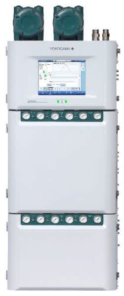
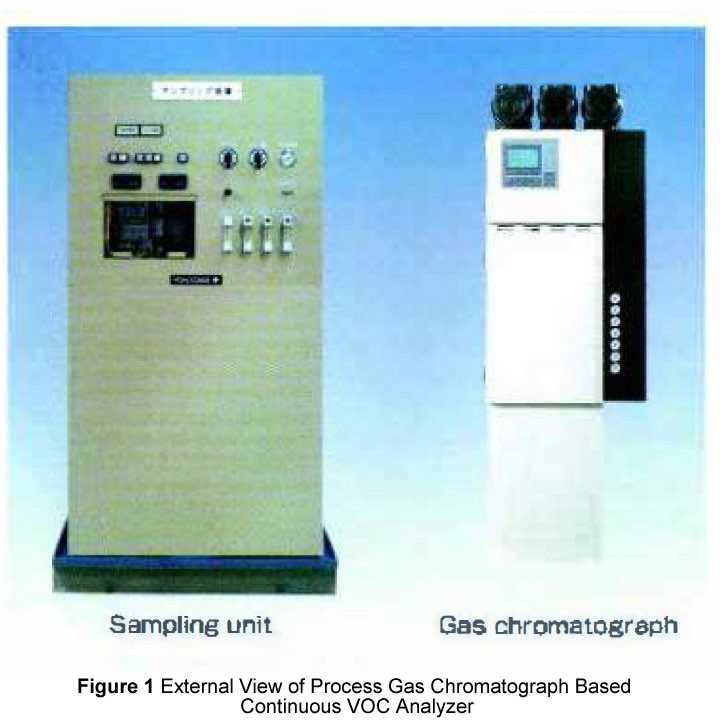 High volumes of volatile organic compounds (VOCs), typified by trichloroethylene and tetrachloroethylene, have long been used in various industrial fields for their high degrees of industrial usefulness. On the other hand, there is a growing awareness of environment preservation today, and of the fact that we face serious environmental pollution due to such harmful VOCs. Industries are increasingly active in recovering and preserving the global environment-attempting to clean polluted soil and ground water, minimize emissions from places of business where VOCs are used, and monitor raw water in water purification plants. Accordingly, in many industrial fields there is the need for measuring and monitoring the concentration of such a pollutant as VOCs. Nonetheless, sampling and analysis tasks remain dependent on human labor in most cases. In view of this situation, we have developed a field-installed system for automatically and continuously measuring VOCs in air and water. With the system, we aim to make the activities of preserving and recovering the global environmental more efficient, less labor-intensive and more reliable, by making active use of high-quality surveillance information. Fundamental technologies that support the system are the process gas chromatograph for separating and measuring the constituents of a small amount of VOC, the compact photoionization detector (PID) for quickly detecting a small amount of VOC in air, and the sparging column for continuously sampling VOCs in water. In this article, we will briefly explain these component technologies, the family of products and their applications. Then, we will introduce a process gas chromatograph based continuous VOC analyzer and a Pill-based continuous total- VOC analyzer. Figure 1 shows an external view of the process gas chromatograph based continuous VOC analyzer.
VOC Measurement Technology, Family of Products and Their Applications
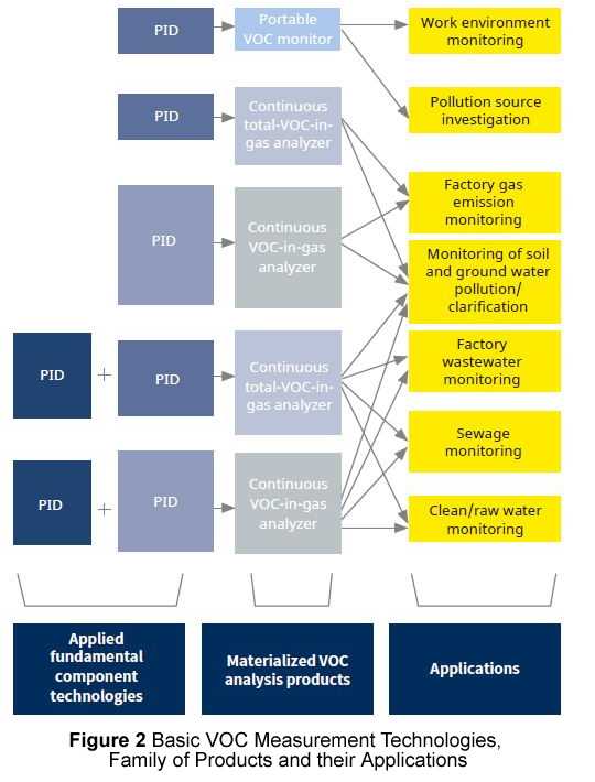 Figure 2 schematically shows the fundamental VOC measurement technologies, the family of products based on combinations of the technologies, and their applications. The PID technology has no capability of constituent-by constituent measurement. This technology is applied to portable VOC monitors and simple and stationary continuous VOC analyzers. In contrast, a gas chromatograph capable of measuring VOCs constituent by constituent is used for applications in which the concentration of a particular constituent in a multicomponent sample is measured or multiple constituents are simultaneously measured. As an environmental pollutant, VOCs are ubiquitous and found not only in air but in soil, rivers, and ground water. Thus, in cases where VOCs are viewed as a measurement object, each measurement project must be able to deal with all possible morphologies of each VOC sample. For this reason, we have developed a continuous VOCs-in-water sampling column for the measurement of VOCs in water. This column, in combination with the PID or gas chromatograph, makes it possible to support all sorts of application, irrespective of whether the sample is a VOC in air or VOC in water. Specific applications include monitoring raw water and sewage in a water purification plant, emissions within a factory, soil and ground water under purification, and a work environment.
Process Gas Chromatograph Based Continuous VOC Analyzer
As a highly reliable online continuous VOC analyzer, Yokogawa's process gas chromatograph has an excellent track record in the field of oil refinery and ethylene processing. A combination of this process gas chromatograph with a VOC sampling unit composes a continuous VOC analyzer. The analyzer thus configured has come into use for continuous monitoring of small amounts of VOC in raw water supplied to a water purification plant or government-regulated VOCs in factory wastewater.
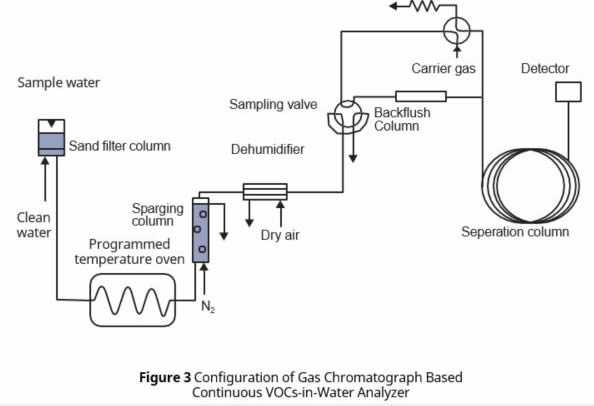
VOCs sampled from the sparging-based continuous VOCs in water sampling column are introduced to the process gas chromatograph for continuous analysis. In the gas chromatograph, a certain amount of sample gas is admitted by a sampling valve and introduced to a separation column as the sample gas is driven forward by a carrier gas (nitrogen).
In the separation column, the sample gas is separated, constituent by constituent, according to a difference in the speed of elution. Chromatograms are obtained as each VOC separated by a flame ionization detector (FID) at the outlet of the separation column is detected in a time-series manner. Thus, the analyzer continuously measures the concentration of each VOC by automatically repeating the above-noted cycle of operation. By using a programmed temperature column as the separation column, it is possible to simultaneously separate and measure a wide range of VOC constituents, from low boiling point constituents to high boiling point constituents.

temperature of the sparging column and the flow rates of the sample water and nitrogen gas. This means the column serves as a continuous VOCs-in-water sampling column capable of supporting quantitative analysis.
Figure 5 shows an example of separating and measuring 21 types of VOC constituents in water, each having a concentration of IO μg/C, by using the process gas chromatograph based continuous VOC analyzer. The figure indicates that each constituent is separated and measured with adequate levels of sensitivity.
PID-BasedContinuousTotal-VOCAnalyzer
There is a case where the sample being measured has a simple, known composition of constituents and the concentration of the constituent in question can be determined by measuring the concentrations of all VOCs, rather than measuring the concentration of that particular constituent only. In that case, it is possible to realize a continuous VOC analyzer that is compact, simple and superior in operability and maintainability, by using a PID. In the case of monitoring and cleaning VOCs in soil or water, pollutants are most often limited to such compounds as trichloroethylene and tetrachloroethylene1.
Consequently, the degree of purification and the operating condition of purification equipment can be automatically and continuously monitored by simply checking the concentrations of all these VOCs.
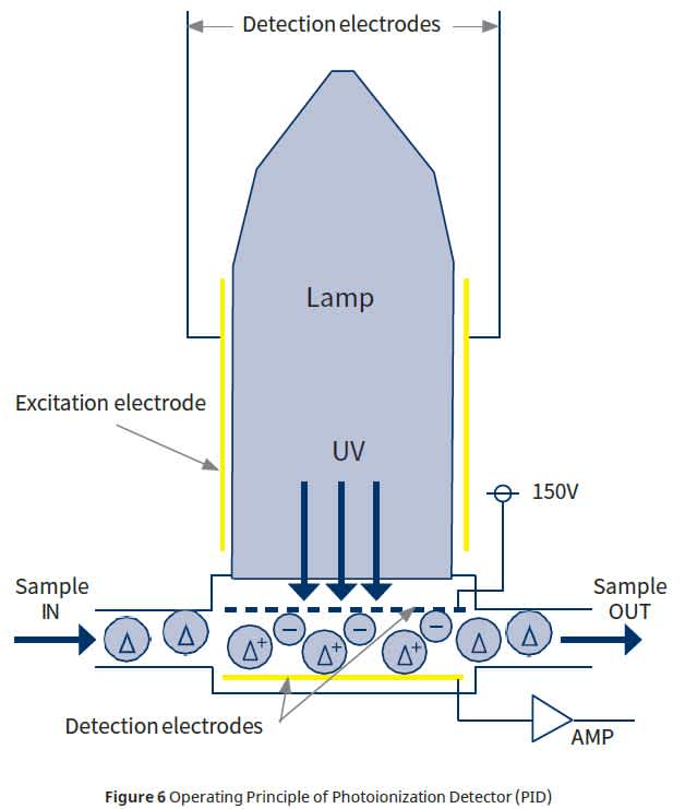
Although benzene, trichloroethylene and other major harmful VOCs are ionized, such major constituents in air as nitrogen, oxygen, carbon dioxide, methane and water have high ionization energy and therefore are not detected. This is why the PID serves as a VOC detector. This VOC detector is a compact yet high performance device, featuring excellent characteristics on the order of seconds and detection sensitivity on a parts-per-billion scale.
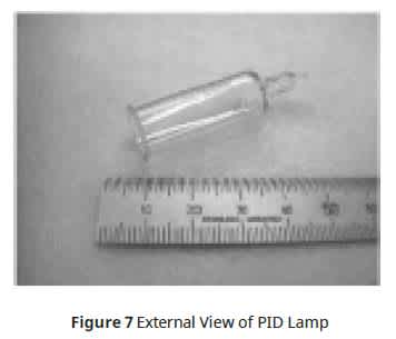
Figure 7 is a picture showing an external view of the lamp used with the PID. The lamp is a simple, gas-filled lamp having no internal electrodes. Accordingly, it has a service life of greater than one year and can be easily replaced. Figure 8 shows an external view of the continuous total-VOC analyzer for soil gases, prototyped by using the PID module discussed above.
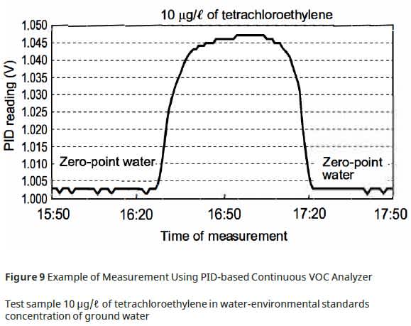
The PID-based continuous total-VOC-in-water analyzer has been realized by connecting the above-mentioned continuous VOCs-in-water sampling column to the front stage of the analyzer for soil gases. Figure 9 shows an example of measuring 10 μg/l of tetrachloroethylene, i.e., environmental-standards concentration, using the analyzer.
The figure indicates that the concentration was measured with an adequate SIN ratio.
 Summary
In this whitepaper, we have introduced our component technologies for continuous VOC measurement the process gas chromatograph, photoionization detector (PID), and continuous VOCs-in-water sampling column. We expect that high-quality environment preservation and recovery activities will be promoted through the proliferation and active use of these technologies. We also hope that environmental clarification will be further accelerated on a global scale.
Key Benefits
In 2010, the GC1000 Mark II was replaced with the GC8000.
■ Intuitive touchscreen HMI
■ Intuitive HMI allows for easy navigation from screen to
screen
■ User friendly display makes interpreting process data quick and easy
■ Multiple ovens and gas chromatograph module (GCM)
■ Parallel chromatography reduces cycle times
■ High-sensitivity thermal conductivity detectors (TCDs)
■ Fewer measurements require FID’s and FPD’s
■ Reduces maintenance and operational costs
■ Extends life to over 1 million cycles
■ Easily maintained and replaced
■ Pressure regulators mounted in oven
■ Electronic pressure compensation is not required
■ Reduces cost and overall analyzer complexity

References
(1) AMEMIYA M. et al. “GC1000 Process Gas Chromatograph” Yokogawa Technical Report English Edition
No. 19, 1994, p.36-43
(2) ASANO K. et al. “GC1000 Analyzer-Bus System” Yokogawa Technical Report English Edition No.
22, 1996, p. 42-45
Industries
-
Oil & Gas Downstream
The oil & gas downstream industry has been facing an increasing number of challenges in recent years. These include the changing characteristics of the feedstock to be processed, aging of process facilities and equipment, rising cost of energy, lack of skilled plant operators who can run a refinery safely and efficiently, and the ever-changing requirements from both the market and the customer.
Over the years, Yokogawa has partnered with many downstream companies to provide industrial solutions focused on solving these challenges and problems. Yokogawa's VigilantPlant solutions have helped plant owners to achieve maximum profitability and sustainable safety within their plants.
-
Refining
In the ever-changing marketplace, refineries are seen not only as crude processing units but also as profit centers. At the same time, there is a keen awareness of the need for safety at such facilities. A total production solution that encompasses planning, scheduling, management, and control is required to achieve long-term goals for profitability, efficiency, and environmental protection. With years of expertise in the automation field, Yokogawa can bring you affordable total solutions for improved operability and a cleaner world.
Related Products & Solutions
-
GC1000 Mark II
The ability to perform discrete separation and positive identification of components and measurement of the composition without interference is an advantage of the gas chromatograph. The process gas chromatograph is widely used in many industries.
-
Process Gas Chromatograph GC8000
Streamline plant operations with user friendly interfaces
-
Gas Analyzers
Enhance efficiency and product quality with real-time analysis
-
Process Gas Chromatographs
Streamline analysis and maintenance
Have Questions?
Contact a Yokogawa Expert to learn how we can help you solve your challenges.

