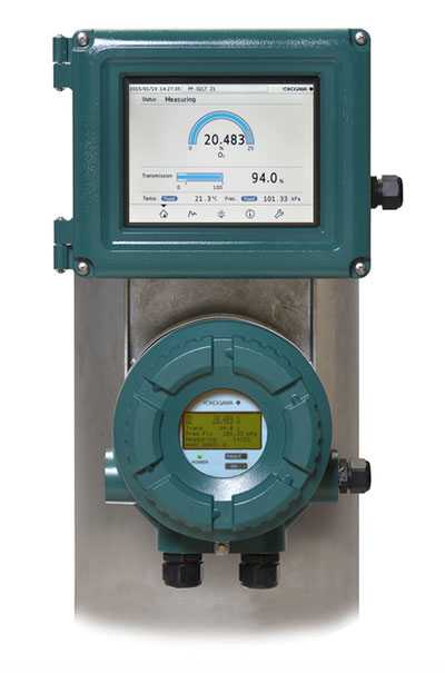
The new TDLS8000 houses all of the industry’s leading features in one robust device. The platform design is for in situ measurements, eliminating the need for sample extraction and conditioning. The non-contacting sensor allows for a variety of process types including corrosive, abrasive, and condensing.
The first generation platform has been proven in many others for the measurements of O2, CO, CH4, NH3, H2O and many more NIR absorbing gases. This second generation platform has improved reliability and ease of installation and maintenance while still meeting or exceeding designed application demands.
What Is the In-Situ Gas Analyzer TDLS8000?
An industry proven laser analyzer designed specifically to meet all of your requirements in one robust device that is easy to operate and maintain.
Features
- SIL2 TruePeak combined with smart laser Technology
- Intuitive touchscreen HMI
- HART and Modbus TCP communications standard
- 8-stage auto-gain adapts to difficult applications
- Fully field repairable with 50 days of data and spectra storage
- Compact design for one-man installation without sacrificing ruggedness
- Area classification Zone2/Div2 or Zone1/Div1
What Are the Benefits of the In-Situ Gas Analyzer TDLS8000?
System Configuration
Standard System Configuration
HART communication available
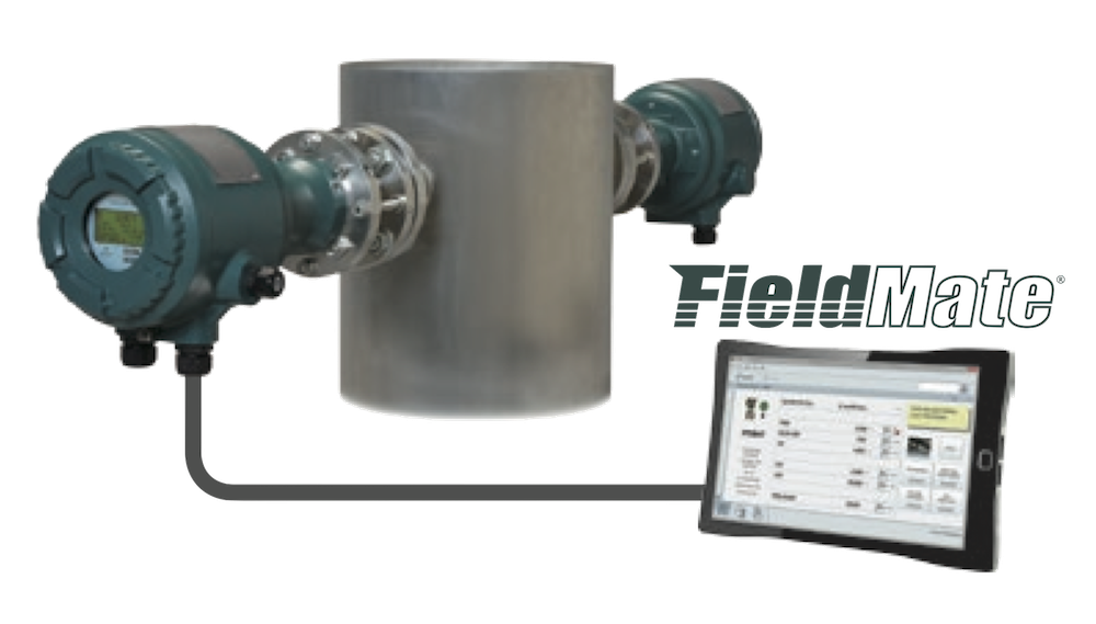
System Configuration with HMI
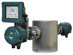
Multi Analyzer Configuration with Remote HMI
Up to 4 units connection available

High Reliability
 Reference Cell
Internal reference cell in the laser module ensures peak locking during trace measurement.
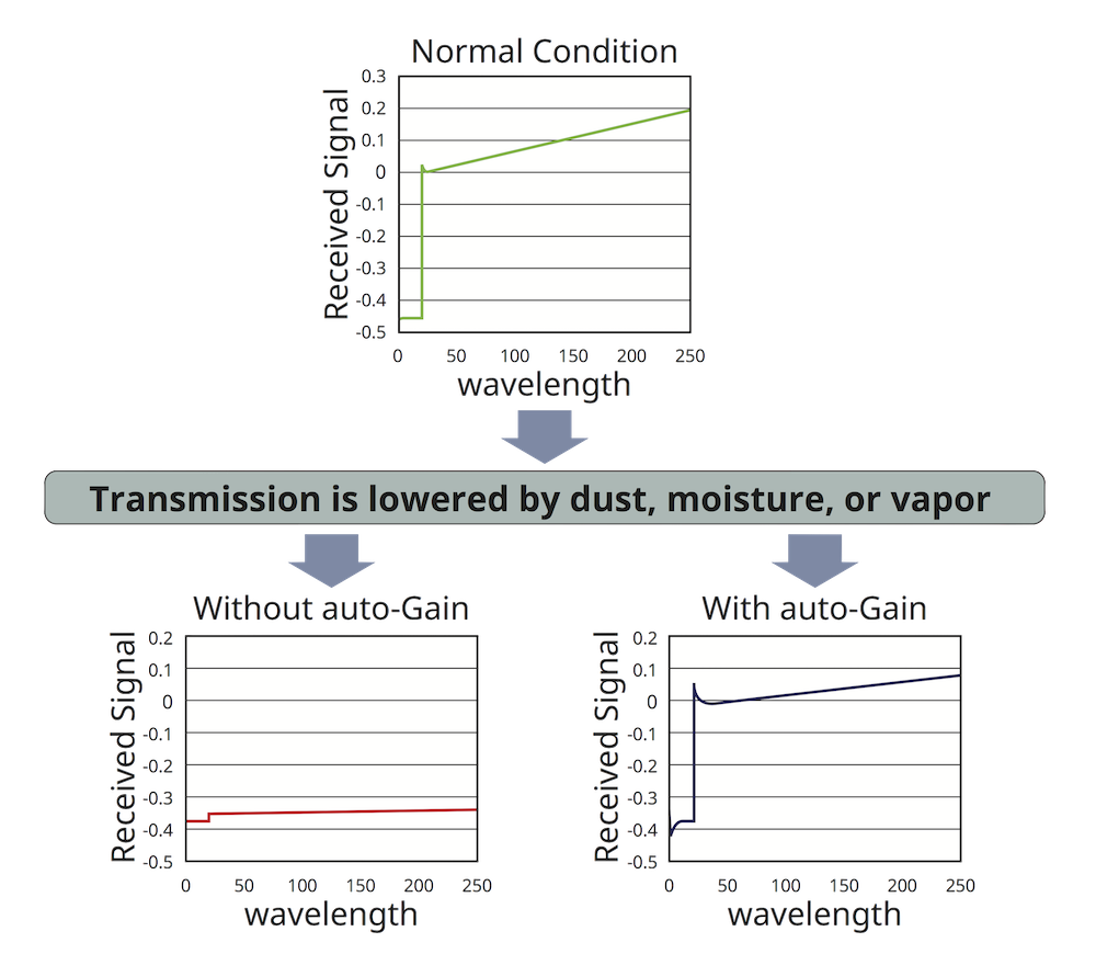
Auto gain
Auto-gain enables wide signal ranges against dynamic variation of transmission.
Validation
Validation can be initiated manually, remotely, or automatically on a daily, weekly or monthly basis defined by the user.
SIL2 certified
IEC61508 SIL designed & approved, SIL2 capability for single analyzer use, SIL3 capability for dual analyzer use.
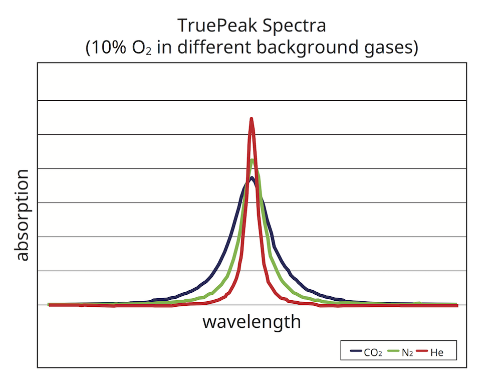
TruePeak
The TruePeak we can measure the area of the absorbance peak. This eliminates effects from changing background gases, allowing for simple pressure and temperature compensation.

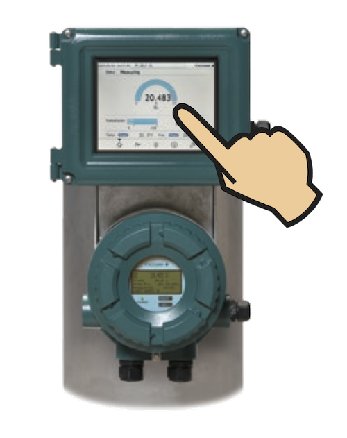
Intuitive touchscreen HMI
Touch screen 7.5 inch color LCD on HMI
- Makes it simple to operate
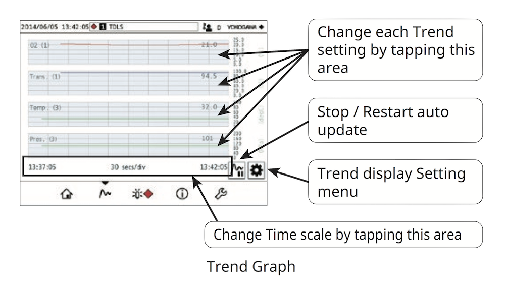
- Gives all the information including trend graph and eliminate PC to maintenance
- Can be remotely installed
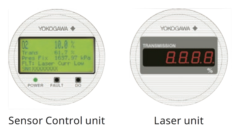
Mini Display
Optical transmission at both the ends for easy alignment
Detalles
Standard Specifications
| Measurement object | O2, CO, CO or CH4, CO2, CO + CO2, H2O, NH3, NH3 + H2O, H2S, HCl concentration in combustion exhaust gas and process gas | |||
|---|---|---|---|---|
| Measurement system | Tunable diode laser spectroscopy | |||
| Measured components and range | Measured component | Min. range | Max. range | |
| O2 | 0-1% | 0-25% | ||
| CO(ppm) | 0-200 ppm | 0-10,000 ppm | ||
| CO+CH4 | CO | 0-200 ppm | 0-10,000 ppm | |
| CH4 | 0-5 % | |||
| NH3 | 0-30 ppm | 0-50,000 ppm | ||
| H2O (ppm) in non HC | 0-30 ppm | 0-30,000 ppm | ||
| H2O (ppm) in HC | 0-30 ppm | 0-30,000 ppm | ||
| CO (%) | 0-20 % | 0-50 % | ||
| CO (%) + CO2 (%) | 0-30 % | 0-100 % | ||
| NH3 + H2O | NH3 | 0-30 ppm | 0-5,000 ppm | |
| H2O | 0-5 % | 0-50 % | ||
| H2S | 0-5 % | 0-100 % | ||
| CO2 (%) High Range | 0-1 % | 0-5 % | ||
| CO2 (%) Extend.Range | 0-30 % | 0-50 % | ||
| H2O (%) | 0-10 % | 0-100 % | ||
| HCl | 0-50 ppm | 0-5,000 ppm | ||
| Output path length | Optical distance between the laser unit and the sensor control unit Standard; 0.5 to 6 m, Max; 30 m | |||
| Output signal | 2 points, 4 to 20 mA DC Output types; Gas concentration, Transmission, Process gas temperature, Process gas pressure Output range; 3.0 to 21.6 mA DC |
|||
| Digital communication | HART, Ethernet | |||
| Contact outputs | 2 points, contact rating 24 V DC, 1 A DO; Function: Activate during Warning / Calibration / Validation / Warm up / Maintenance conditions Fault; Function: Activate during normal condition, not activate during fault condition or when the system power is off |
|||
| Valve control output | 2 points Function; Activate calibration or validation solenoid valves for zero, span or validation gas Output signal; 24 V DC, 500 mA Max. per terminal |
|||
| Alarm | Warning; Gas concentration low/high, Transmission low, Process pressure low/high, Process temperature low/high, Validation required, Validation failure, Zero/Span calibration error, Non process alarm, External alarm Fault; Laser module temperature low/high, Laser temperature low/high, Detector signal high, Peak center out of range, Reference peak height low, Absorption too high, Transmission lost, Reference transmission low, Reference peak height high, Laser unit failure, Laser module error, File access error, E2PROM access error. |
|||
| Contact inputs (Digital input) |
2 points Function; External alarm/Calibration start/Validation start/Stream switch Contact specification; Zero voltage contact input Input signal; Open signal; 100 kΩ or more, Close signal; 200 Ω or less |
|||
| Input signal (Analog input) |
2 points, 4 to 24 mA DC Input types; Process gas temperature, Process gas pressure |
|||
| Self-diagnostics | Laser Unit temperature, Sensor Control Unit temperature, Laser temperature, Detector signal level, Memory read/write function, Peak locking condition | |||
| Calibration | Calibration method; Zero/Span calibration Calibration mode; Manual, Auto, Local initiate (HMI) |
|||
| Validation | Validation method; Up to 2 points Validation mode; Manual, Auto, Local initiate (HMI) |
|||
| Power supply | 24 V DC ±10% | |||
| Warm-up time | 5 min. | |||
| Protection degree | IP66, NEMA Type 4X | |||
| Hazardous area classifications | Division 1, Zone 1; Explosion-proof/ Flame-proof type; FM, cFM, ATEX, IECEx (Pending) Division 2, Zone 2; Non-Incendive/Type n; FM, cFM, ATEX, IECEx |
|||
| Process gas condition | Process gas temperature; Maximum 1500℃ Process gas pressure; Max. 1 MPa, Min. 90 kPa Dust in process gas; 20 g/m3 or less |
|||
| Installation condition | Ambient operating temperature; -20 to 55℃ Storage temperature; -30 to 70℃ Humidity; 0 to 95%RH at 40℃ (Non-condensing) Mounting flange type; ASME B 16.5, DIN, JIS Gas connections; 1/4 NPT or Rc1/4 Purge gas; Recommended purge gasses O2 analyzer; N2 (99.99% or greater, application dependent) H2O ppm analyzer; N2 (99.99% or greater with < 20 ppm H2O for feed to the optional dryer package) CO, CO or CH4, CO2, CO+CO2, NH3, NH3+H2O, H2S, HCl; N2 (99.99% or greater, application dependent) or Instrument air CO, NH3 analyzer: N2 (99.99% or greater, application dependent) or Instrument air Purge gas flow rates; 5-20 L/min for optic 5-30 L/min for process window Purge gas connections; 1/4NPT (-G1, -C2, -D2, -C2, -D1, -C1), Rc1/4 (-G2, -S2, -E2, -J2, -E1, -J1) |
|||
Performance
| Measurement gas | Repeatability | Linearity | |
|---|---|---|---|
| O2 | ± 1% reading or ± 0.01% O2, whichever is greater | ± 1% F.S. | |
| CO (ppm) | ± 2% reading or ± 1 ppm CO, whichever is greater | ± 1% F.S. | |
| CO + CH4 | CO | ± 1% reading or ± 1 ppm CO, whichever is greater | ± 2% F.S. |
| CH4 | ± 4% reading or ± 0.02% CH4, whichever is greater | ± 4% F.S. | |
| NH3 | ± 2% reading or ± 1 ppm NH3, whichever is greater | ± 2% F.S. | |
| H2O (ppm) in non HC |
± 2% reading or ± 0.1 ppm H2O, whichever is greater | ± 1% F.S. | |
| H2O (ppm) in HC | ± 2% reading or ± 0.1 ppm H2O, whichever is greater | ± 1% F.S. | |
| CO (%) | ± 1% reading or ± 0.01% CO, whichever is greater | ± 1% F.S. | |
| CO (%) + CO2 (%) | CO | ± 1% reading or ± 0.1% CO, whichever is greater | ± 1% F.S. |
| CO2 | ± 1% reading or ± 0.1% CO2, whichever is greater | ± 1% F.S. | |
| NH3 + H2O | NH3 | ± 2% reading or ± 1 ppm NH3, whichever is greater | ± 2% F.S. |
| H2O | ± 4% reading or ± 0.05% H2O, whichever is greater | ± 2% F.S. | |
| H2S | ± 1% reading or ± 0.005% H2S, whichever is greater | ± 1% F.S. | |
| CO2 (%) High Range | ± 1% reading or ± 0.005% CO2, whichever is greater | ± 1% F.S. | |
| CO2 (%) Extend. Range | ± 1% reading or ± 0.02% CO2, whichever is greater | ± 1% F.S. | |
| H2O (%) | ± 1% reading or ± 0.004% H2O, whichever is greater | ± 1% F.S. | |
| HCL | ± 1% reading or ± 2.5 ppm H2O, whichever is greater | ± 2% F.S. | |
YH8000 HMI Unit
The YH8000 is a HMI designed specifically for the Tunable Diode Laser Gas Analyzer, the TDLS8000.
- Touchscreen 7.5 inch color LCD on HMI
- Makes it simple to operate
- Can be remotely installed
- Up to 4 units connection available
Specification
| Display | Touchscreen 7.5 inch TFT color LCD panel, 640 x 480 (VGA) |
|---|---|
| Communication | Ethernet; RJ-45 connector, Communication speed; 100 Mbps |
| Protection degree of enclosure |
IP65, NEMA Type 4X |
| Weight | 4 kg |
| Mounting | Analyzer mount (Front, left-side, right-side) with tilt function, Pipe mount or Panel mount |
| Cable Entries | 1/2NPT or M20 x 2 |
| Installation conditions |
Ambient operating temperature; -20 to 55℃ Storage temperature: -30 to 70℃ Humidity: 10 to 90%RH at 40℃ (Noncondensing) |
| Power Supply | 24 V DC ±10% |
| Hazardous area classifications |
Division 2, Zone2: Non-Incendive/Type n; FM, cFM, ATEX, IECEx |
The simple and robust TDLS8000 assures the reliable and less maintenance operation of the analysis.
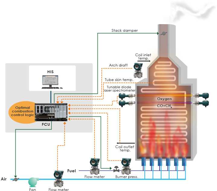
Fired Heater Combustion Safety and Lifecycle Management
Yokogawa TDSL8000 and CO + CH4 measurements provide reliable information to achieve:
- Combustion efficiency improvement
- Safety improvement
- Longer lifetime of the coils and coil hangers
- Higher throughout of the process heating
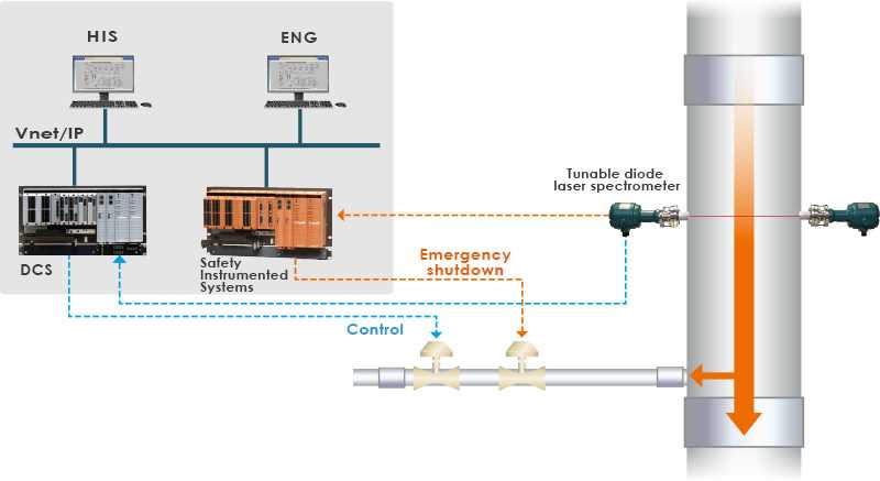
Limited O2 Concentration
O2 Measurement for Safety and Process Monitoring & Control Yokogawa TDLS8000 02 analyzer achieves:
- No sampling system operation
- Fast response analysis
- No interference analysis
- Less maintenance operation
Recursos
Fired heaters are used for various processes in oil refining and petrochemical plants.
Ensure minor issues in Vinyl Chloride Production can be identified before becoming serious problems with Yokogawa’s In-Situ Gas Analyzer TDLS8000 and Probe Type Analyzer TDLS8200.
En el mantenimiento y la administración de plantas industriales, monitoreo del pH de las aguas residuales / ORP es a la vez una obligación legal y una necesidad necesaria para la protección del medio ambiente. El Monitoreo sin estar atento puede llevar a consecuencias graves.
Es necesario el manejo de H2S del gas de escape en calderas de recuperación de lejía negra para cumplir con las normativas ambientales.
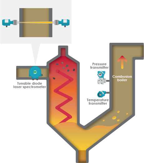
Tomando en cuenta las cuestiones ambientales y de seguridad tales como la eficiencia de combustión y la disminución de NOX y CO en los gases de escape, se ha vuelto importante para controlar la concentración de O2 en los procesos de incineración de basura.
NH3 injection lowers NOx in stack flue gas, boosts dust collection efficiency, and prevents erosion. Precise measurement and control of NH3 are crucial to avoid excess use, which increases costs and causes odors. The TDLS8000 solves these issues with direct measurement for effective NH3 management.
Electrolysis plants create hydrogen and chlorine from a brine solution. Chlorine gas generated from the anolyte of the electrolysis tank generally contains between 0.5 to 2.0 vol% H2O. The sample is then cooled and filtered to remove brine, subsequently coming out as wet chlorine gas. The wet gas is sent to a drying tower where it is treated with sulfuric acid to get moisture down to the ppm level.
La sosa cáustica y ácido clorhídrico, producida en las plantas electrolizadoras, son materiales fundamentales utilizados en varias industrias; químicas, farmacéuticas, petroquímicas, pulpa y papeles, etc. El beneficio es el resultado de la producción efectiva con costos de explotación/mantenimiento mínimos. El control adecuado del proceso genera estabilizado productos de calidad estables con una gran ganancia operativa.
O2 measurement is used to safely recover flue gas containing a high concentration of CO from a converter furnace. With conventional paramagnetic oxygen analyzers, O2 concentrations are obtained through a sampling system to recovery flue gas. Therefore, there are problems with the maintenance and running costs of the sampling system, and time delays in measurement.
In this eBook we explain how to improve fired heaters safety & efficiency by controlling combustion using TDLS technology. Download it now and learn:
- The 4 top industry challenges related to fired heaters
- How to efficiently and safely manage combustion
- How TDLS technology can improve operational excellence in fired heaters
Spectrometric technology can assess many critical characteristics about products, but it has limits. It can be challenging to determine when the line has been crossed
With fired heaters, users hope to get greater efficiency and reduced emissions but often are disappointed. Given the number of fired heaters operating every day and their importance in the process industries, any improvements realized across the board will have huge impacts. More units can reach their potential with some simple changes in work practices and technology upgrades.
SABIC Turns to Yokogawa TDLS Analyzers to Enhance Safety Functions and Production
Documentos y Descargas
Videos
Yokogawa’s new TDLS8000 houses all of the industry’s leading features in one robust device. The platform design is for in situ measurements which negate the need for sample extraction and conditioning. The non-contacting sensor allows for a variety of process types including corrosive, abrasive and condensing. The first generation platform has been proven in many others for the measurements of O2, CO, CH4, NH3, H2O and many more NIR absorbing gases. This second generation platform has improved reliability and ease of installation and maintenance while still meeting or exceeding designed application demands.
Noticias
-
Nota de Prensa nov. 22, 2015 Yokogawa Corporation of America Releases TDLS8000 Tunable Diode Laser Spectrometer
¿En busca de información adicional sobre Yokogawa Iberia, tecnología y soluciones?
Contáctenos


