Sebastián Cúneo
sebastian.cuneo@soteica.com
Diego Ruiz
diego.ruiz@soteica.com
Abstract
Refining and petrochemical industries operate complex energy systems based on several steam pressure levels, with fired boilers producing high pressure steam and burning different fuels, cogeneration of steam and electricity, dealing with fuel gas production/consumption imbalances, external fuels and electricity imports/exports with their corresponding commercial contracts and finally having to comply with many environmental constraints. Different economic trade-offs provide many challenges to operate the site wide energy system at minimum cost. For instance, the trade-offs among electrical power, steam and fuels networks. This paper discusses real industrial examples in which the sitewide utilities system of refinery and petrochemical Sites are optimized with a real time, on line, industrially proven software.
The same software technology provides online calculation of the Energy and Emissions Key Performance Indicators. They are all based on measurements that are validated with an overall online mass and energy balance model. Experiences gained during more than 20 years of industrial projects deployed worldwide are commented. Main project steps are explained and critical details to be taken into account to assure successful use and proper technology transfer are presented. Specific case studies will be discussed in the paper. Open loop vs Closed loop implementation is also presented.
Introduction
Refineries and petrochemical plants usually operate large and complex utilities and energy systems. They burn several type of fuels, operate cogeneration units to supplement the electric power purchases or export electricity, need to provide several steam pressure levels to different types of consumers and observe emission limits.
In almost all of the cases, these complex utilities and energy systems have several degrees of freedom. Proper manipulation of the degrees of freedom with the aid of cost-based optimization software can result in significant operating cost savings. Since the electrical system represents one of the main economic trade-offs with the steam system, electrical deregulation provides many new challenges to operate the overall combined energy system at minimum cost.
Other important aspects are that utilities systems are continuously evolving (changes are frequent) and that sometimes, there is a lack of sensors and measurement errors that needs to be addressed properly.
Moreover, utilities systems have several constraints that come usually from the operational and contractual sides. For example, minimum and maximum steam production capacity in the boilers, the need to maintain a steam production cushion due to safety reasons, or the fuels and electric power quotas and penalties.
Finally, it is important to mention that traditionally, given the complexity of the systems, the optimization of the utilities is often managed at the level of each individual Plant or Area. But the optimization of each individual Area does not necessarily give the true overall site optimum. Moreover, an attempt to optimize a whole site based on an isolated view of each Plant at a time could be worse than doing nothing.
In the dynamic operational and economical environment of a Plant, implementing the proper actions necessary for the optimum utilities system management can only be done with the aid of an on-line tool. It should execute in an unattended, automated way, providing at any time the right answers to the different users (from operators to engineers), with the man-machine interface appropriate for each one of them.
In order to successfully address all the items mentioned above, a software called Visual MESA has been developed. The original MESA program was developed in the early 1980's. Since the Visual MESA version was released in 1997, it has been implemented in more than 50 sites and is extensively in use to model and optimize the overall site energy and utilities systems.
Experiences gained during more than 20 years of industrial projects deployed worldwide are commented (Refs. 1 to 10 are related to some recent projects). Some examples are explained in the following section.
Industrial Project Examples
The following real industrial projects are presented as examples:
- Medium size refinery complex
• Example of day to day recommendations and their impact - Emissions management
- SO2 /NOx variable constraint
• Medium-size refinery plus olefins complex - Coordination among plant areas to optimize the overall site
• Refinery energy system closed loop optimization
Example 1: Medium size refinery
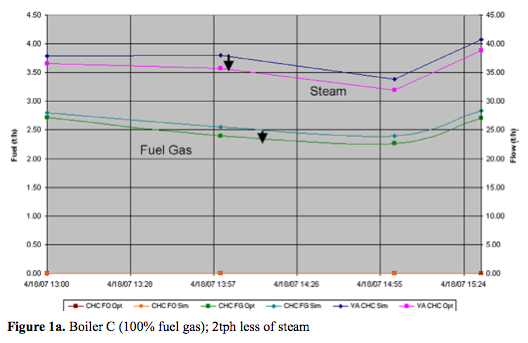
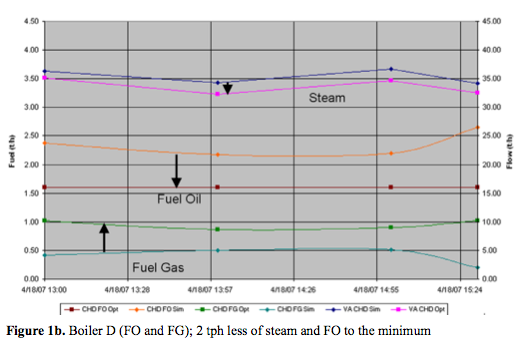
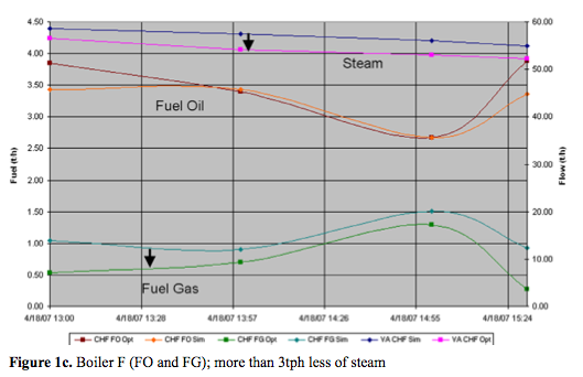
This is an example of the kind of Visual MESA daily recommendations. In a French refinery a set of manual operating recommendations given by the optimizer during a Shift have been (Ref. 6):
- Pump swaps.
- Fuels to boilers (i.e., FG and FO).
As a result of the manual actions, the changes performed by the control system have been:
- Steam production at boilers.
- Letdown and vent rates.
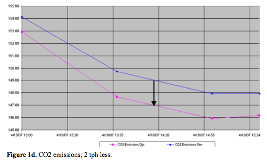
Figures 1a, 2b, 3c and 4d show the impact of the Manually-applied optimisation actions on steam production, fuel use and CO2 emissions reduction.
Obtained benefits can be summarised as follows:
- Almost 1 tph less FO consumed.
- Approx 7 tph less high pressure steam produced.
- Approx 2 tph less CO2 emitted.
- Approx 200 kW more electricity imported (which was the lowest cost energy available).
Example 2: Emissions management
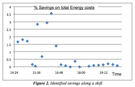
Figure 2 shows an example of the savings found in a refinery during a shift time frame (savings are expressed as a % of the total energy costs). Each point in the plot corresponds to an automatic Visual MESA execution. Note the decrease in the potential savings when operators begin to apply the recommendations (last three hours of the shown shift) meaning the savings were truly captured.
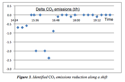
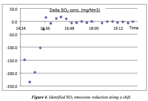
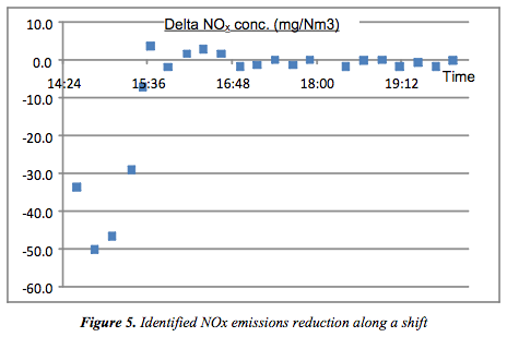
Figures 3, 4 and 5 show respectively the corresponding potential reduction in CO2 emissions (t/h), SO2 and NOx emissions (in terms of concentration with data corresponding to one of the main stacks) found during the same operational shift period applying the optimization recommendations.
Energy costs reduction in the order of 3% on total energy costs were obtained in this particular example. They imply an associated reduction in CO2 emissions, in the order of 2 t/h. Additionally, and in this case also due to fuel management, a reduction in SO2 (200mg/Nm3 less) and in NOx (50 mg/Nm3 less) in one of the main stacks has been also obtained.
This example shows the effect of the optimization by using an online model which includes the emissions when the limit depends on fuels liquid/gas ratio.
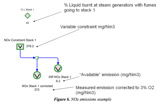
When optimizing the ratio changes, so the emission limit also changes:

In this case, an increase in the % of liquid burnt, as result of the total energy cost system optimization, implies an increase in the corresponding emissions. However, in the case of SO2 emission, the system will work even further from the emission limit (the new emission limit is higher). In the case of NOx, the system will operate at its new emission limit (while the simulation case was 6 mg/Nm3 far from this limit.
Example 3: Medium-size refinery plus olefins complex
The Repsol YPF Tarragona Refinery, located in Spain, with a refining capacity of eight million tons per year of crude oil, operates a large and complex utilities system. The refinery shares its utilities system with a neighboring Olefins Plant (ref. 2) and is optimized as a whole.
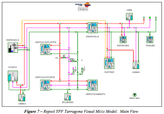
A complete model of the utilities system of the overall site was built (see Figure 7). The model contains the entire steam, boiler feed water, condensate and power systems. Steam is generated in several different units, with conventional boilers, gas turbine heat recovery steam generators and two cogeneration units.
The five steam pressure levels were modeled and all the units considered in high detail, including all the consumers and suppliers to the respective steam, BFW and condensate headers.
Detailed efficiency curves of the biggest turbines were included in the model and they are adjusted continuously with on-line validated data.
Since Visual MESA is an operations-oriented tool, the proper training of the operating personnel is a very important project step. The different shifts have been trained by using the finally deployed model. Inputs gathered from the operators during and after the training class have been very valuable to improve the reports and other displayed information.
When analyzing the optimization recommendations, a foreman with coverage of the whole Refinery, Utilities and Olefins Units was the person with responsibilities to coordinate the overall optimization implementation on a day-to-day basis.
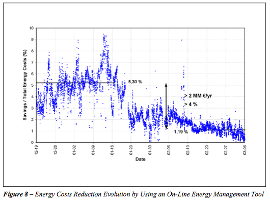
In order to evaluate with accuracy the economic benefits obtained with the use of this tool, the following real-time test has been done:
- First month: Base Line - Visual MESA being executed on-line, predicting the potential benefits but no optimization actions are taken.
- Second month: Operators trained and optimization suggestions are gradually implemented.
- Third month: Optimization recommendations are followed on a daily basis.
Figure 8 shows the results of this test. Over that period, annualized savings of more than 2 MM €/year were measured.
Example 4: Closed loop optimization
The fourth example corresponds to a Dutch refinery where the Visual MESA online optimisation runs in closed loop, the so-called energy real time optimiser (Ref. 5). Typical optimisation handles include letdowns, load boilers steam flow, gas turbine generators/steam turbine generators power, natural gas intake, gas turbine heat recovery, steam generators duct firing, extraction of dual outlet turbines, deaerator pressure, motor/turbine switches, etc.
Typical constraints are the steam balances at each pressure level, boiler firing capacities, fuel network constraints, refinery emissions (SO2, NOx, etc.) and contract constraints (for both fuel and electric power sell/purchase contracts). Benefits are reported to come from the load allocation optimisation between boilers, optimised extraction/condensing ratio of the dual outlet turbines, optimised mix of discretionary fuel sales/purchase, optimised gas turbine power as a function of fuel and electricity purchase contract complexities (trade off between fuel contract verses electricity contract penalties).
Typical optimization variables and constraints (Open Loop vs Closed Loop)
The following set of handles is usually used to reduce energy costs with the existing utilities system equipment:
- Fuels to fired boilers (e.g. Fuel Oil and Fuel Gas)
- Fuels to process heaters / furnaces (e.g. Fuel Oil and Fuel Gas)
- Reposition fuel to Fuel Gas network (e.g. LPG and Natural Gas)
- Fuel Gas Flaring
- Fuels to supplemental firing at Co-generation units
- Steam generation at fired boilers, including boilers balancing
- Steam letdowns
- Steam vents
- Steam turbogenerators management (inlet, extraction, outlet, condensing) and corresponding electricity generation
• Steam turbines that drives compressors management (load, extraction, induction, outlet, condensing)
- Heat Recovery Steam generators at Gas Turbine Co-Generation units
- Gas Turbine load at Co-Generation and corresponding electricity generation
- Steam injection to Gas Turbines
- Air conditioning for Gas Turbines
- Pump swaps (steam turbine and electrical motor drives options)
- Electricity import / export, dealing with market spot prices
- FCC Turboexpander loads
Such a set of typical optimization variables can be divided in two main groups:
- Continuous variables, such as steam production from a fired boiler, gas turbine supplemental firing and/or steam flow through a steam-driven turbo generator. Those variables can be automatically manipulated by the optimiser acting on the proper set points of the DCS. So they can be implemented in open loop or in closed loop.
- Discrete variables, where the optimiser has to decide if a particular piece of equipment will operate or not. The most common occurrence of this kind of optimisation in refinery steam systems is spared pump optimisation where there is the need to choose which of two pumps to operate, one of which is driven by a steam turbine and the other by an electric motor. Those variables cannot be automatically manipulated. They need the operator's manual action to be implemented. So they can only be implemented in open loop.
The constraints that usually need to be followed are:
- Processes energy demand
- Burners capacity
- Emissions limits and quotas
- Compressors power demand
- Contractual constraints (e.g. Natural Gas and electricity supply, including quantities and pricing contracts)
Installation Architecture
The software has two types of uses:
- Stand-Alone use (Engineering station)
- Client-Server use (Engineering, Shift Supervisors, Operators and Managers stations)
The purpose of the Stand-alone use (Engineering station) is for individual users to be able to run case studies on their own PCs, using the current site model or any other model the user may have built to perform what-if studies. The models can be populated with current, real time data, or historical data (very easily acquired from the Plant Information System via standard OPC Historical Data Access). Multiple parametric runs can be programmed and launched from within MS Excel, writing back the desired model values and reading optimization results also from there.
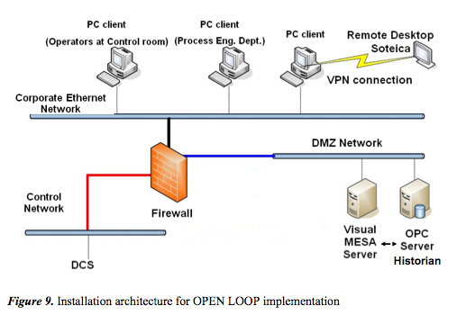
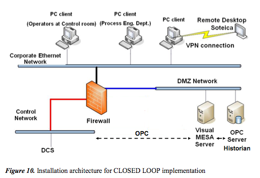
The purpose of the Client-Server use is to share the solutions of the current, online optimization, between multiple users throughout the organization. The Visual MESA server runs as a service on a given PC, connected to the real time data base via OPC, as mentioned before. It automatically runs with no interruption every 15 minutes, writing results back to the Plant Information System and generating reports. Any PC connected to the plant network can be configured to access the model and the reports. Users can connect in many ways (html and Excel reports, Graphical User Interface).
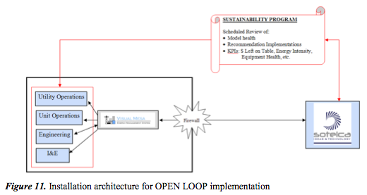
Figure 9 shows an example of the scheme of the information and control network for an Open loop implementation and the location of Visual MESA server and PC clients. Figure 10 shows an example of the scheme of the information and control network for a Closed loop implementation and the location of Visual MESA server and PC clients. Note that the difference is the possibility of writing to DCS via OPC from Visual MESA server.
Key technological features for closed implementation
The three most relevant steps to close the loop by using a real time optimizer are:
- Model validation
- Optimization
- Set Point implementation
Model validation step consists in checking the data, the balances and determine if the optimization can be applied. The main aspects of this step are:
- Data validation
- Solve a simulation case for parameters calculations
- Optimization Pruning
- Steady State Detection
Data validation includes the checks of the measurements limits, the controller status, the optimizers (decision variables) and mass balances.
As part of model validation, a set of parameters are calculated by solving a simulation (mass and energy balances) and tuning performance parameters (i.e. equipment efficiencies, etc.).
An important aspect of the model validation is the optimization pruning, that is, to remove or lock the optimizers (decision variables) or constraints because of the quality of the data related to them.
The steady state detection is based on a procedure using key variables' fast fourier transforms (FFT) to identify main process variables steadiness. Optimization algorithm should be robust enough to always give a feasible solution. Visual MESA optimization algorithm is highly tuned for steam and power optimization.
Set Point implementation requires repeating the steady data validation and steady state detection, looking for the optimizer limit changes and controller mode changes. Only very carefully selected set points are written to the control system. The change in the set point is only done after careful tests and the Set Point ramping is done on the DCS.
Typical Project Schedule
A typical project schedule includes the following main steps:
- Kick-Off Meeting
- Control System Review
- Off-Site Model Building
- Mid-Point Review
- Burn-In Period
- Commissioning Visit
Kick Off Meeting
During this step data collection is done. This includes the Piping and Instruments Diagrams, a tags list from the Real Time Database (plant information system) and equipment data sheets. Software installation and connection to the Plant Information system is done at the beginning of the project.
Control System Review
A review of the steam, power, and fuel control systems with knowledgeable experts is performed. The goals of this Control System review are:
- Develop a list of variables already controlled and how Visual MESA needs to relate to them.
- Identify any needed new control strategies or changes to existing strategies to implement optimization.
As a result, the optimization suggestions can be achieved properly through the existing operating procedures and control strategies and structure.
Off-Site Model Building
A complete model of the overall Energy System is built. The model includes the whole fuel, steam, boiler feed water, condensate and electrical systems.
All the steam pressure levels are modeled as well as all the production units utilities network, with a high level of detail including all the consumers and suppliers to the respective steam, boiler feed water and condensate headers. Electricity and fuel supply contract details are easily included in the model, with the electricity market cost updated from the real time data base system tags, when available.
The fuel gas network is usually also modeled, as it is involved with the steam and power generation equipment and all its constraints and degrees of freedoms are also taken into account by Visual MESA. A well-tuned model would generally be run at Level 3, with a run at Level 4 once in a while to evaluate potential operational changes.
The objective function Visual MESA optimizes is the total operating cost of the system, which is:
Total Operating Cost = Total Fuel Cost + Total Electric Cost + Σ Miscellaneous Costs
The SQP optimizer's job is to minimize this objective function subject to operating constraints in the system.
Total Fuel Cost is determined from the fuel use of each boiler and combustion turbine multiplied by their respective fuel prices. Total Electric Cost is determined from the net electric use of each motor, load, and generator multiplied by their respective electric prices. The electric generation (power selling) is just negative electric use. The model can take into account the electricity price corresponding to the actual hour of the day as well as the penalties associated to selling more or less power than the market arranged exportation amount, if any.
Miscellaneous Costs are normally used to charge for demineralised water coming into the system, but can be used for any other cost related to the energy system (for example CO2 emission cost). Calculations to model and optimize CO2 emission cost are also developed and run together with the electric, steam and fuel optimization and help choose the best fuel to use in boilers and gas turbines taking into account the emission costs. A standard feature of the software, the "constituents" can be used to model the emission produced by each type of fuel.
Mid-Point Review
The model and optimization configuration is reviewed with users. Training at engineering and users' level is performed, including the following items:
- Basic skills (model navigation and menus)
- Optimization
- Monitoring capabilities
- Case studies ("What If?" planning)
- Building models
- Building custom reports
- Software architecture
Burn-In Period
Model fine tuning and optimization results analysis is performed on a daily basis. Minor model modifications and additions or adjustments of constraints are done. At the end of this period, operators start using the tool every day.
Commissioning Visit
The model is in use by Operations for site-wide costs minimization and as the energy watch dog. Economic benefits already obtained are reviewed and improvements for the future are discussed.
Key Performance Indicators
In addition to the main purpose of the real time online optimization, appropriate performance metrics can also be identified and performance targets can be set during the real time energy management project. Also, within the model calculation and reporting infrastructure, corrective actions in the case of detected deviations from target performance can be recommended.
Those metrics are usually known as Key Performance Indicators (KPI's) and can be:
- High level KPIs that monitor site performance and are geared toward use by site and corporate management. For example: Total cost of the utilities system, predicted benefits, main steam headers imbalances, emissions, etc.
- Unit level KPIs that monitor individual unit performance and are geared toward use by unit management and technical specialists. For example: plant or area costs, boilers and heaters efficiencies, condensate recovery percentage, use of energy per unit of production, etc.
The metrics are intended to be used in a Site Monitoring and Targeting program where actual performance is tracked against targets in a timely manner, with deviations triggering a corrective response that results in savings. Two of the main KPIs written back to the real time data base by Visual MESA are the Energy System economics and calculated efficiencies.
Each time the system is executed, the potential gap between the current operating the costs and the minimum operating costs is calculated. The savings associated with this gap will be materialized only if all the suggested optimization movements are implemented simultaneously. These predicted savings constitute one of the main economic KPIs.
It is expected that, if the operators implement all the proposed recommendations on a continuous basis, the potential gap will start decreasing over time. If in the future the system is in a new condition, a new potential gap will re-appear until the operators make the optimizing movements, and the cycle is repeated. If the projected savings are consistently high, this should prompt Management, Supervision and/or Engineering staff to identify any issue that is impeding the capture of the costs reduction.
Most commonly historized equipment efficiencies are: Boilers and heaters efficiency, Gas Turbines Heat Recovery Steam Generation systems (HRSGs) efficiencies, and Gas Turbines heat rate. Their long term trends help to identify those pieces of equipment that can lose efficiency over time and therefore justify cleaning, when possible.
Headers imbalances are also usually historized (the software automatically calculates the mass imbalances for each header where a special Visual MESA ad-hoc calculation block, called "balloon" is located). Also, the headers imbalances are often related to sensor failures. A sudden increase of an imbalance would trigger the search for the cause. If a bad signal sensor or an out of range signal is identified, it would need to be repaired and or re-ranged.
Sustainability Program
A proactive support program, which is underway for many of our clients, with the goal of ensuring that the benefits of the project are sustained and that the health of the model is kept in check over time is very important.
This advanced sustainability program is achieved by Soteica having remote access to the solution in order to conduct monthly audits of the models. Thanks to this program it has been possible to avoid the short term obsolescence that this type of systems usually suffers. Also, when personnel changes occur, Soteica acts as a transition back-up until the new resource is in place and trained avoiding discontinuity in the usage of the solution. Under the Sustainability program the communication between the technology supplier and the end user becomes very fluid enabling the refinery personnel to develop the necessary skills in order to modify and revamp existing models on their own, as well as using the tool for planning and investment decisions via case studies.
When refiners identify that the Total Cost of Ownership, including the sustainability services, has paybacks of less than 6 months they concur that keeping advanced technologies such as Energy Real Time Optimization up and running and evergreen is a logical step. Not only is it profitable but it allows the refinery to operate at minimum energy cost and within emissions constraints, 24x7x365.
Conclusions
An on-line model for industrial energy management has been presented, along with the experiences gained on several successful projects. Energy cost reductions have been obtained taking advantage of the Visual MESA software functionalities. It demonstrated to be a robust optimizer and very well suited to be used on-line, providing optimization recommendations to the operators on a routine basis.
These projects have allowed the understanding of all the decision variables and the associated constraints, which sometimes are hidden or ignored.
Additionally, the centralization of the responsibilities for the energy system's optimal operation has been achieved. A proactive support program is underway with the goal of ensuring that the benefits of the projects are sustained and that the health of the model is kept in check over time.
It is important to emphasize the high involvement and motivation of plant operators found since the very beginning of the implementation projects. Coordination among plant areas in order to implement the proposed optimization recommendations is also a critical issue, so management involvement is crucial. The robustness of the tool helped operators to gain confidence on the overall optimization system.
Finally, users' acceptance and widespread use, for both engineers and operators, is one of the key issues for a successful implementation.
References
- "Auditing and control of energy costs in a large refinery by using an on line tool", D. Ruiz, C. Ruiz, J. Mamprin, Depto. de Energías y Efluentes Petronor, (2005), ERTC Asset Maximisation Conference organized by Global Technology Forum, May 23-25, 2005, Budapest.
- "Reducing refinery energy costs", Ruiz D., Ruiz C., Nelson D., Roseme G., Lázaro M. and Sartaguda M., (2006), Petroleum Technology Quarterly, Q1 2006, pages 103-105.
- "Online energy management", S. Benedicto, B. Garrote, D. Ruiz, J. Mamprin and C. Ruiz, Petroleum Technology Quarterly Q1 2007, pages 131-138.
- "The Use of an On-line model for Energy Site-Wide Costs Minimisation", García Casas, J.M., Kihn, M., Ruiz D. and Ruiz C., (2007), ERTC Asset Maximisation Conference organized by Global Technology Forum, May 21-23, 2007, Rome.
- "Energy System Real Time Optimization", D. Uztürk, H. D. Franklin, J. M. Righi, A. T. Georgiou, NPRA Plant Automation and Decision Support Conference, Phoenix, USA, 2006.
- "Site-wide Energy Costs Reduction at TOTAL Feyzin Refinery", Département Procédés - Energie, Logistique, Utilités, TOTAL - Raffinerie de Feyzin, D. Ruiz, J. Mamprin and C. Ruiz, (2007), ERTC 12th Annual Meeting organized by Global Technology Forum, 19-21 November, Barcelona.
- "Online Energy Management", D. Ruiz, C. Ruiz, D. Nelson, Hydrocarbon Engineering, September 2007, pages 60-68.
- "A Watchdog System for Energy Efficiency and CO2 Emissions Reduction", Diego Ruiz, Carlos A. Ruiz, European Refining Technology Conference (ERTC) Sustainable Refining, Brussels, Belgium, April 2008.
- "Online energy costs optimizer at petrochemical plant", Marcos Kihn, Diego Ruiz, Carlos Ruiz, Antonio García Nogales, Hydrocarbon Engineering, May 2008, Pages 119-123.
- "Finding Benefits by Modeling and Optimizing Steam and Power Systems", M. Reid, C. Harper, C. Hayes, Industrial Energy Technology Conference (IETC), New Orleans, May 2008.
Iparágak
-
Alap vegyi ágazat
Yokogawa has been serving the bulk chemical market globally and is the recognized leader in this market. With products, solutions, and industry expertise, Yokogawa understands your market and production needs and will work with you to provide a reliable, and cost effective solution through the lifecycle of your plant.
-
Finomítás
In the ever changing marketplace, refineries are seen not only as crude processing units but also as profit centers. At the same time, there is a keen awareness of the need for safety at such facilities. A total production solution that encompasses planning, scheduling, management, and control is required to achieve long-term goals for profitability, efficiency, and environmental protection. With years of expertise in the automation field, Yokogawa can bring you affordable total solutions for improved operability and a cleaner world.
-
Olaj és gáz feldolgozói ágazat
The oil & gas downstream industry has been facing an increasing number of challenges in recent years. These include the changing characteristics of the feedstock to be processed, aging of process facilities and equipment, rising cost of energy, lack of skilled plant operators who can run a refinery safely and efficiently, and the ever-changing requirements from both the market and the customer.
Over the years, Yokogawa has partnered with many downstream companies to provide industrial solutions focused on solving these challenges and problems. Yokogawa's VigilantPlant solutions have helped plant owners to achieve maximum profitability and sustainable safety within their plants.
-
Petrolkémiai
Petrochemical companies’ needs are extremely diverse. To come out ahead in today’s highly competitive marketplace, producers are striving to improve quality and productivity. Yokogawa provides tailor-made solutions for these needs based on its long and wide-ranging experience in this field.
-
Vegyi
Chemical plants rely on continuous and batch production processes, each posing different requirements for a control system. A continuous process calls for a robust and stable control system that will not fail and cause the shutdown of a production line, whereas the emphasis with a batch process is on having a control system that allows great flexibility in making adjustments to formulas, procedures, and the like. Both kinds of systems need to be managed in available quality history of product, and to be able to execute non-routine operations. With its extensive product portfolio, experienced systems engineers, and global sales and service network, Yokogawa has a solution for every plant process.
-
Ömlesztett és petrolkémiai anyagok
Whether you produce petrochemicals, inorganics or intermediates, chemical companies are under cost and margin pressures to deliver products in a timely and efficient manner while maintaining safe and compliant operations. Additionally, chemical companies need to adjust to fluctuating feedstock and energy prices and to provide the most profitable product mix to the market.
Yokogawa has been serving the automation needs of the bulk chemical market globally and is the recognized leader in this market. With products, solutions, and industry expertise, Yokogawa understands your market and production needs and will work with you to provide a reliable, and cost effective solution through the lifecycle of your plant.